Improvement in Zn utilization in the Zinc Coating process to reduce specific consumption
We studied and optimized the Zinc coating process using an Arc Spray gun so that Zn wastage can be reduced during the coating operation on ductile iron pipe in the Tata Metalliks (TM) plant. The zinc is normally applied automatically by traversing a multiple of arc spray heads over a rotating pipe held by cones at both ends. The minimum coating deposition is determined (as per IS:8329) by the traverse and rotating speed of the pipe along with the amount and throughput rate of arc spray heads being used.
Figure 1 shows a schematic diagram of Zn coating on a ductile iron pipe. The coating material that is used in this process is introduced in the form of two electrically conductive consumable wires. The below figure shows the schematic of the wire-arc spraying nozzle and the part of the setup of the Zn coating process, which is used at Tata Metaliks (TM).
The gun geometry is designed in such a way that the wire tips are separated by a distance of about a few tenths of a millimeter from one another. An electric voltage is applied on the two wires, which causes an arc in the tip's gap and produces a thin layer of molten Zn. A stream of atomizing gas, as shown in the above figure, strips the molten layer off the wire tips and propels it toward the pipe surface. The detached molten droplets undergo further atomization to produce smaller droplets, which are deposited on the substrate one over another, where they solidify and form a coating layer. This process involves many complex phenomena, such as the interaction of molten metal droplets with the surrounding atmosphere through convection, impingement of molten metal droplets on the substrate, and phase change of droplets involving the latent heat release.
Indeed, there is no literature available on the mathematical modelling of metal coating on a rotating surface such as a pipe (in this case). This study has been done using Ansys Fluent.
Validation of the model:
A comparison between the ad hoc experiments and numerical pressure results is shown on the left side of figure 2(a) below. It can be observed from the plot that a reasonable match between the ad hoc experiment and numerical results is obtained, providing some confidence in a developed numerical model to use for further study. Another comparison with gas velocity contours for a mass-flow-rate of 0.0123 kg/s is shown on the right side of figure 2(b) below. The left image (in this figure) represents the velocity contour from ref. (Amir Hossein Pourmousa Abkenar, PhD Thesis, University of Toronto, 2007) and the right image represents the velocity contour of the present simulation.
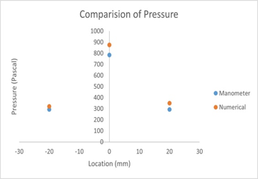
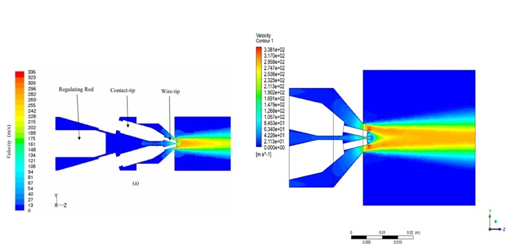
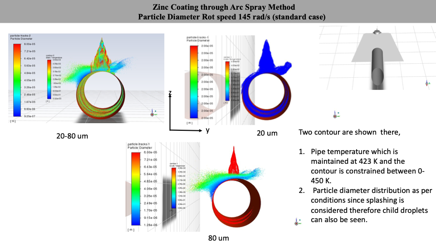
Figure 3 shows the distribution of temperature of particles and particle distribution due to splashing (except in 20 µm size particles where splashing is not considered). Pipe temperature is maintained at 423K, and for better visualization of temperature, it is constrained to 450K. The figure shows clearly how the child droplets are generated after hitting the pipe surface. Lower-diameter particles achieve low temperatures very fast and may get solidified in the flight before they reach the surface of the pipe.
In the actual Zn coating process, the spray gun is located at an angle, as shown in figure 4 below. Some results of this geometry are shown below.
Effect of spray distance:
Velocity Contour
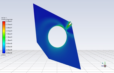
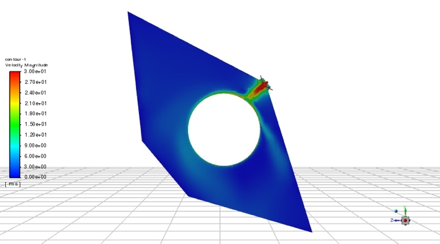
Figure 4 shows the air velocity contours for different spray distances. It is observed that when the spray distance is decreased, the flow is diverted away from the nozzle significantly, which may reduce the nozzle clogging.
Wall film thickness
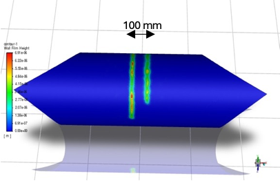
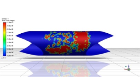
Figure 5 shows the Zn coating thickness which is obtained under two spray distances. From this figure, the maximum thickness (about 6.9 µm) is obtained for the case of 245mm spray distance, while it is about 0.1 µm when the distance is reduced to 200mm. Also, in reduced spray distance, the film thickness is not uniform/continuous but broken in structure. It is observed that the critical parameter here is adhesion correlation.
For further details, queries, or publications related to this research, please contact us through our contact information on the website.