|
SILICON CARBIDE MANUFACTURING |
|
|
Fig. 1: The Acheson process (a) during operation and (b) cross-section of the furnace after the reaction
|
|
| The Acheson process which is used for the production of silicon carbide, uses petroleum coke and quartz as major raw materials to produce SiC in bulk quantities. SiC is formed by carbothermal reduction process in the heat resistance furnace (Acheson furnace). Figure 1 shows some typical photographs captured during and after the experiment. The area inside the circle in figure 1(b) shows the formation of green-colored SiC. Whereas, outside the circle partially reacted/unreacted materials were found. SiC has extreme hardness, sharpness and good thermal properties and hence it is employed as an abrasive and refractory material. |
Figure 2. |
|
The
main raw materials are SiO2 and C which are made
to react at a high
temperature. Saw dust and salt (sometimes) are also added, so that saw dust burns
and provides pores, facilitating the escape of evolved gases (at high
temperature). Firing is done for about 40 hours and after cooling, the
side walls are removed. An outer layer of uncombined mixture is broken
away, exposing the cylindrical mass of sharp, brilliant crystals. A
schematic cross sectional view of the resistor furnace, after cooling, is given
in Figure 2. The whole reaction
process is very complex and the productivity is low. About 11-15% of total
charge is converted into SiC while theoretically it can go up to 42%. Obviously,
the process is inefficient and has high potential for improvement. We have
studied this process extensively both theoretically and experimentally and have
increased its efficiency substantially. Figure 3 shows morphology of the SiC
produced during one of the experiments.
Figure 3: SEM micrographs of samples collected after an experiment (a) 1cm, (b) 2cm, (c) 3cm and (d) 4cm away from the electrode surface in the right side direction.
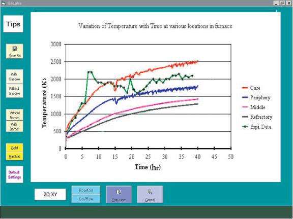
We have developed a robust 1-D and 2-D mathematical models considering conduction, convection and radiation as heat transfer modes. Finite Volume Method has been employed to solve the heat balance equations. To validate the model, an experimental facility has been developed at laboratory scale. Both model and experimental data show a good agreement with each other. A Graphical User Interface for the process has also been developed (Figures 3 and 4).
Figure 3. GUI developed for the Acheson process to plot the results in contours form.
Figure 4. GUI developed for the Acheson process to plot the results.
The technology and sofware are available for industries/individual to use. Interested industries/person can contact us. For further details or queries or publication related to this, kindly contact us at the address given on the web-site. |
|